
 Atlanta geotech contractors Lift It Rite were contacted by Deas Construction regarding the settlement of parking lot pavement behind the loading docks at a manufacturing plant in Norcross, GA. The following observations were made during this first visit:
- An area of concrete slab pavement, approximately 75’ x 25’, surrounding a crane and a steel rack showed signs of settlement.
- Holes drilled in random spots within the 75’ x 25’ area revealed voids up to 24” directly beneath the slab.
- Manual probing of the soil indicated it was quite soft.
Calculations were made for filling the voids and lifting the slab using high-density polyurethane, the DOT's product for highway stabilization and bridge approach slab leveling. However, it was agreed that further investigation into this settlement's cause was warranted before proposing the void fill and lift. Ground Consolidation Services of Tucker, GA, was asked to come in and do some GPR (ground-penetrating radar) readings and DCP (dynamic cone penetrometer) testing to determine the compaction of the soil. Results indicated the following:
- Confirmation of voids beneath the concrete slab. When core holes were drilled to accommodate the DCP cone, the cores fell into the voids under the slab.
- GPR readings are difficult in clayey soils, but shallow subsurface voids were detected, especially around the 12’ diameter brick manhole.
- Penetrometer results, measured in blow counts, indicated very soft soils down to 28’ in some places.
- Very soft soil was detected around the 12’ diameter brick manhole.
At this point, it was determined that the root cause of the slabs' and voids' settlement must be an infrastructure infiltration issue. Lift It Rite technicians met with Deas Construction on-site for a third visit to inspect the interior of the infrastructure.
Entry was made into a new manhole uphill beside the employee parking lot. This manhole was connected to the 12’ diameter brick manhole (located in the area of settling) by a 72” corrugated metal pipe (CMP). The CMP runs parallel to the back of the facility where the loading docks are located. It is about 16’ deep (below grade of concrete) to the invert of the CMP. Observations were as follows:
- The CMP was in decent shape until you got closer to the area of the concrete slab settlement.
- There were two major breaches in the CMP at the joints. Soil was observed coming through the breaches. These breaches were within the 75’ x 25’ rectangle of sunken concrete.
- The inside of the 12’ diameter brick manhole was in pretty good shape except for the base itself, which was pitted and had voids underneath.
A summary of the testing and the walkthrough/site evaluation indicated that the failure of the 72” CMP culvert joints led to major soil erosion, which in turn led to settlement and undermining of the concrete. Additionally, the base of the 12” diameter brick manhole was pitted and broken, leading to more soil infiltration and settlement around the base.
Powerful Polymers
Lift It Rite employed a variety of specialized materials to address the complex issues at the site. AP Fill 700, manufactured by Alchatek, played a crucial role in sealing pipe joints and deep soil stabilization. This NSF/ANSI 61-approved polyurethane resin features a low viscosity for soil permeation and an impressive 30x expansion factor. Its ability to react with moisture creates a squeezing and compaction effect in the soil, making it ideal for sealing infiltration in stormwater and sewer systems and stabilizing roadways.
Lift It Rite used Alchatek’s AP Lift 475 high-density polyurethane foam for concrete lifting and void filling. This two-component system expands 15x its original volume, creating a strong, watertight support structure. The team used a PMC PHX-40 plural component proportioner capable of 4 gallons per minute output to apply this material. For the CIPP point repairs, Pelican Underground was called in to install fiberglass and felt composite liner impregnated with epoxy resin. This combination creates a structural repair that restores the pipe’s original strength. Lastly, AW Cook supplied a polymer-modified concrete patching material to rebuild and provide a new wearable surface for the brick manhole base.
Painless Procedures
A proposal was made for a three-step repair:
- Lifting and void-filling the concrete slabs with high-density polyurethane.
- Permeation and pressure grouting of the soils with single-component geotechnical hydrophobic polyurethane resin.
- CIPP point repairs of the two breaches in the CMP and concrete repair for the 12’ diameter brick manhole base.
The proposal was accepted, and the work was done during September and October 2021. The sequence of the work and details were as follows:
CMP (Corrugated Metal Pipe) Joint Injections and Soil Stabilization
Because of the amount of soil coming in through the failing CMP joints, Lift It Rite technicians decided it would be best to seal and encapsulate the joints with expanding polyurethane foam to create a temporary patch until the CIPP point repair contractor could mobilize. This would stop the undermining of the concrete by eliminating the erosion pathways.
The technicians went down through the 12’ diameter manhole and proceeded up the 72” CMP culvert to the failed joints. At four locations, AP Fill 700 was injected in a clock pattern at the failed joints. Injection holes were drilled through the wall of the CMP approximately 12” offset from the joint. The resin was pumped until reacting polyurethane foam refused back through the joint breaches and sealed them off. Once all the joints were sealed, the soil stabilization could proceed.
Two CMP pipe breaches and a brick manhole with infiltration issues occurred within a 75’ x 25’ area. DCP testing detected loose soil down to 28’ below grade. This CMP culvert had a constant flow of water through it, so the surrounding soils were wet and soft, and the soil infiltration into the CMP compounded this. The grout plan would involve permeation/compaction injections to stabilize this block of soil 75’ x 25’ x 28’ deep.
GCS performed additional GPR scanning before the soil stabilization grouting, and Ground Penetrating Radar Services came by to locate the water main and fire hydrant piping.
A grid pattern was laid out with approximately 3-5 foot spacing. Some spacing varied due to obstructions like the steel racks, etc. ABC Concrete Cutting was called in to core the 2” holes to accommodate the next step: forming the holes for the pressure grouting. Over 100 holes were cored in the 72’ x 25’ area.
Geotechnical Contractor GeoLab was called in to use Direct Push technology to form the grout holes with their Geoprobe machine. Because of the clayey soils present, it was possible to press the holes using a 1-3/4” pressing tool and then extract the probe, leaving a 1-3/4” to 28’ deep hole pressed into the soil. 2” x 4’ long steel grout pipes were then hammered into the pressed holes to serve as grout pipes. Each grout pipe was hammered 2-3 feet into the bored hole and then terminated at the top with a high-pressure valve and a quick connect.
The typical application rate for soil stabilization is around 1 gallon per vertical foot. When the polyurethane resin is pumped into a pressed hole, the entire hole is pressurized, and the resin will find the weakest soil zones to penetrate and expand. AP Fill 700 was injected through the entire grid pattern of directly pushed holes using air-powered and gas-powered hydraulic-powered pumps. After 28 gallons were installed per point, the injections were stopped. There was some contractor discretion on site if it was determined one point had looser soil and another area was tight. A few holes could not be pumped because of the grout's migration, and the soil's compaction would cause an adjacent hole to be closed. If a new pipe could be inserted there, the technicians would try and pump it, but typically, once a hole gets filled/squeezed shut, it becomes like rock in there, and the hole cannot be re-bored.
AP Fill 700 was also injected through ½” steel injection probes in a circumferential pattern around the 12’ diameter brick manhole. These were extra injections in addition to the grid pattern to ensure the brick structure was sealed up and the soil around it compacted. Looking down through the opening of the 12’ brick manhole, one can see the reacted grout permeating the loose brick walls.
Slab Lift and Void Fill
Slab lifting and void filling was done using AP Lift 475. DOTs and geotechnical contractors use this type of structural polyurethane nationwide to lift concrete, support slabs, fill voids, and stabilize infrastructure. The high-density poly is a two-component system with an A-side and a B-side chemical. The reaction occurs when the two components meet, resulting in a high-density, watertight polyurethane foam. This product expands 15x by volume, depending on conditions. The equipment used was a PMC PHX-40 plural component proportioner capable of 4 gallons per minute of output.
A grid pattern of approximately 4’ on center was drilled through the 75’ x 25’ slab. Injection holes were 3/8” in diameter. Each injection hole was checked with a probe before injecting poly, and in some areas, the technicians found voids up to 60”. AP Lift 475 was injected beneath the concrete until the voids were filled and the lift was detected. In areas requiring more lift, slab recovery was attempted with more injections. Extra care was taken not to create too much lateral force when injecting around the brick manhole.
A walk-behind concrete saw was brought in to cut the joints and free up binding slabs in the area where more lift was needed. After the joints were freed, the technicians got more lift. The 2” core and 3/8” injection holes were patched with concrete.
CIPP (Cured-In-Place Pipe) Point Repair
Pipe relining specialists from Pelican Underground were called in to perform point repairs on the two failed joints. They ultimately performed four-point repairs. One of the failed joints required two overlapped CIPP repairs. Additionally, they discovered and addressed an additional breach further up the pipeline.
A CIPP point repair is a fiberglass and felt composite liner impregnated with epoxy resin and then pressed into the walls of the host pipe with pneumatic pressure. A CIPP repair is a structural repair, not a patch. That pipe is now as strong as new in those areas.
Before installing the point repair, a bypass pumping system was set up upstream from the repair work. Water was constantly flowing in this CMP, so it was dammed off and pumped (bypass) around the repair work area. After the water was diverted, interior surface prep was performed. This involved cleaning and removing AP Fill 700, which had permeated the pipe and coated the walls and floor, then pressing some of the jagged metal with hydraulics to bend it back into place as much as possible. Sharp edges were also trimmed.
Once this was complete, the point repair liners were assembled. They rolled out the fiberglass liner, coated it with epoxy, combined it with the felt liner, and then wrapped it around an inflatable packer. That entire assembly was lowered through the manhole opening and pulled into place by the crew. Compressed air was applied, and the packer expanded and pressed the CIPP liner into place. The packer was then deflated and removed after the initial cure. This was repeated for each point repair.
The brick manhole with the failing concrete base was then injected through the floor with polyurethane to fill any voids below it and provide support for rebuilding the base. Pelican Underground used a polymer-modified concrete patching material from AW Cook to fill any holes in the base and provide a new wearable surface for the concrete.
Rapid Results
Lift It Rite performed manual compaction testing by going through the 75’ x 25’ grid pattern with a ½” probe to see any loose soil zones. With the manual probe, it was difficult to penetrate the ground, which indicated good compaction and void fill throughout the zone.
Ground Consolidation Services then brought back a dynamic cone penetrometer to do post-project DCP testing in the areas where testing had been done before. DCP results indicated a great increase in bearing capacity. A few shallow core samples were also taken and showed complete fill and compaction.
Ground-penetrating radar was then run along the same scan lines to compare before and after scans; those also showed improvement.
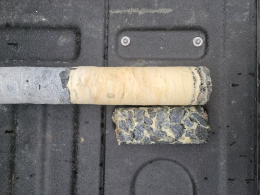
The Upper core sample showed high-density polyurethane that filled the void between the slab and subgrade. The lower core is AP Fill 700 polyurethane binding gravel together. There were areas of gravel encountered on site, and the permeation material glued it together into a solid mass.
Want more information on stabilizing soil with polyurethane?